Sound and Voice Effects
Sound plays an important role in the user experience by adding another layer of depth; making for a more realistic experience. http://www.robotoid.com/sound/soundingoff-sounds.html
- Arduino and piezo ~ dual purpose can make sound or be used as a vibration sensor
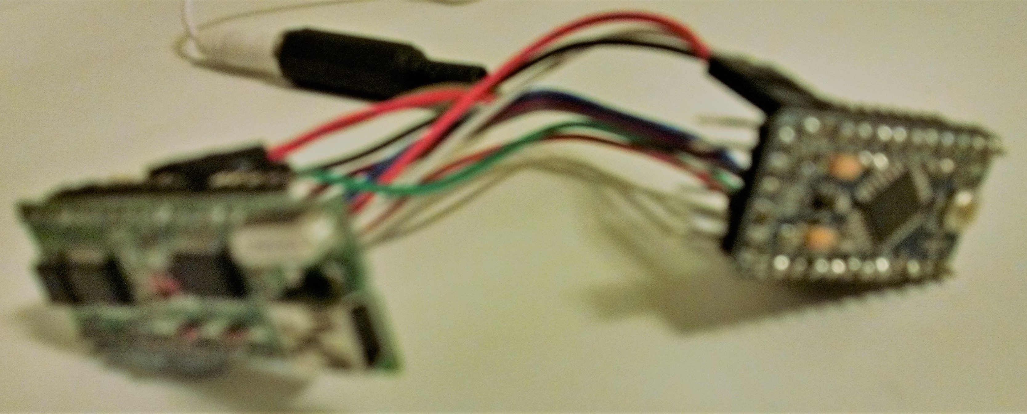
The WT588D is a small audio playback module that stores and plays sound files from a microSD card. You pre-load the sounds you want, wire it to your Arduino, and trigger playback by sending it a simple signal. It handles the digital-to-audio conversion and amplification internally — your Arduino just tells it which track to play.
Low-cost option – WT588D ~ $5
Other options include the Adafruit Audio sound board $20 and mini computer systems on a board, such as Raspberry Pi or similar $30+. These devices also need an SD card to provide memory space, more sensitive to vibrations and use more power.
SoundFX Lightshow
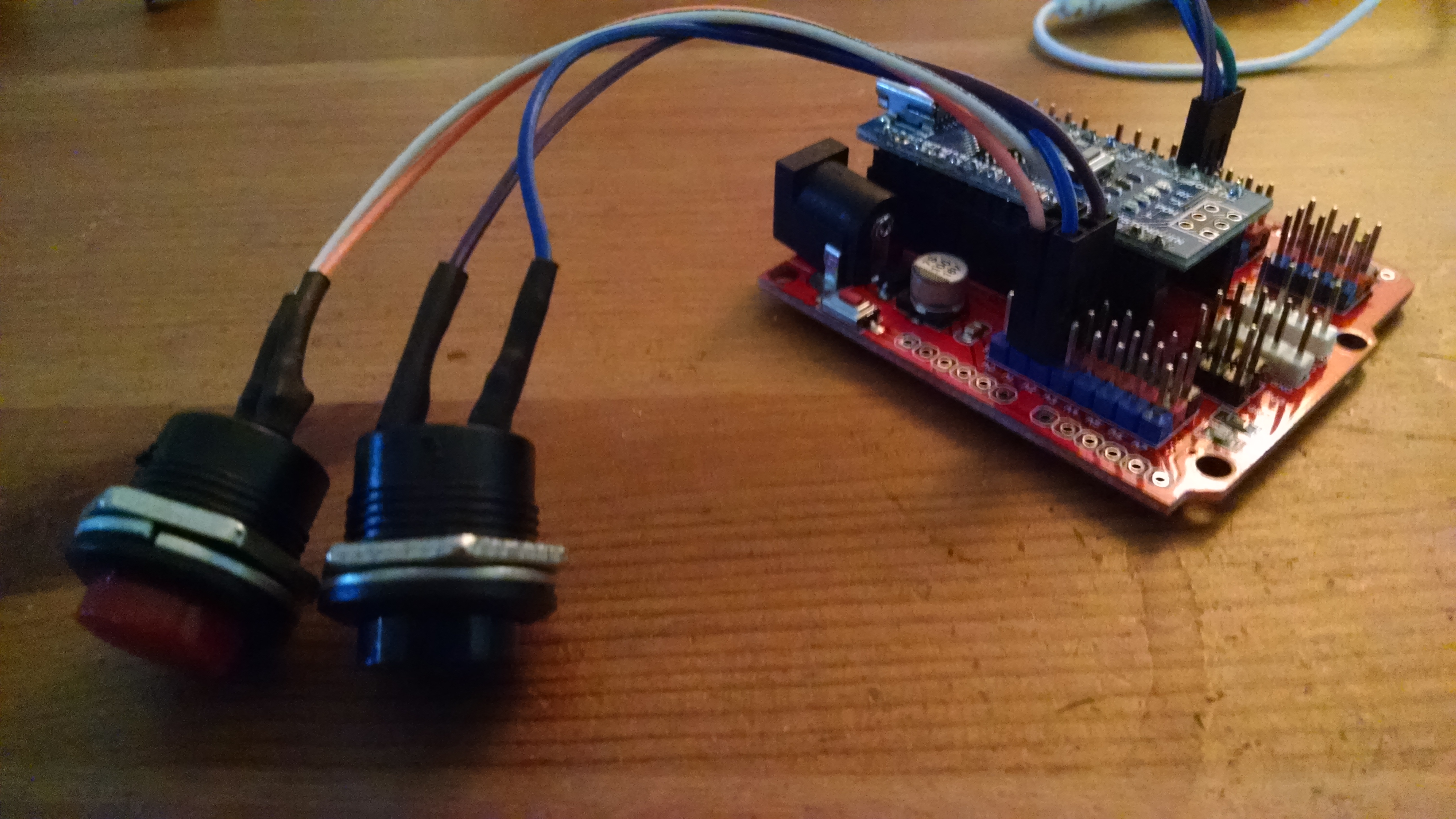
Using an Arduino Nano on an expansion board with push-buttons, one to play a sound and the other to select a sound effect from a WT588D through a speaker.
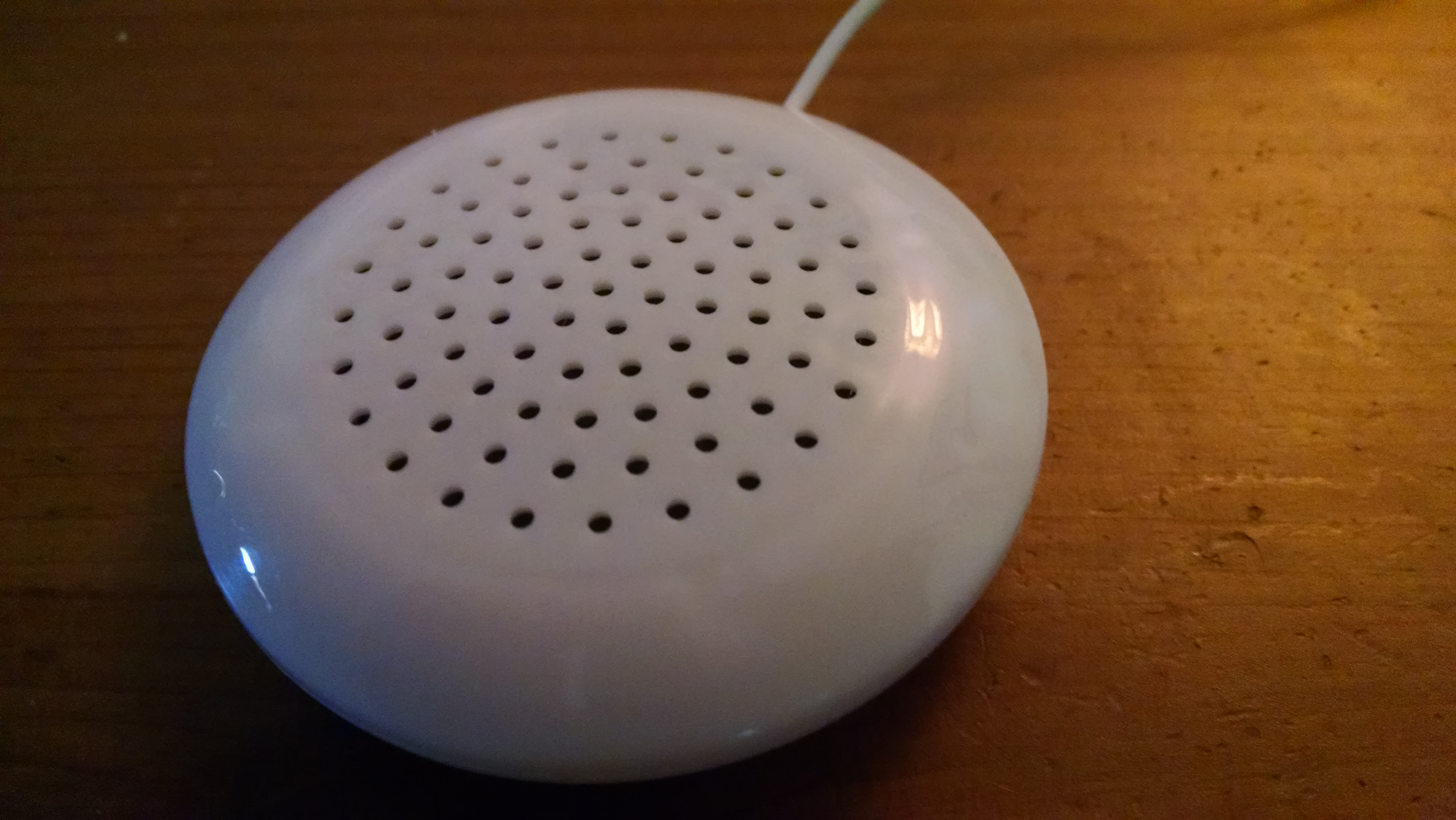
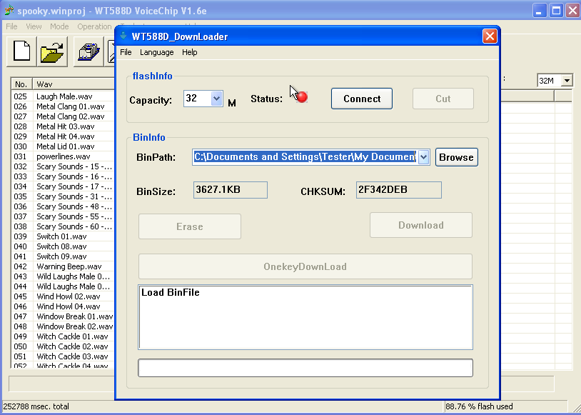
For this project, I’ve selected a low-cost option, internal memory, and reasonable sound quality – WT588D-U, this model includes a built-in mini USB port for power and direct programming. Sound output is amplified by the module and produced by a standard 0.5w 8-ohm speaker or can be connected to an amplified speaker system. The down-side with this module is that it can be difficult to get the programming software and drivers installed and configured.
Using the WT588D voice module connected to a basic speaker, the project can deliver cellular phone quality sound.
More information and tutorials specific to the WT588D:
- https://www.instructables.com/id/WT588D-Standalone-Arduino-sound-player/
- http://www.ars-informatica.ca/eclectic/programming-the-wt588d-sound-module-part-1/
- https://www.instructables.com/id/Getting-the-Most-Out-of-a-WT588D-Sound-Module/
There are several options for triggering a sound clip to play. Examining the documentation for this module including the schematic…The sound module has a few modes to select from when working with it. If there are only a few sounds that need to be triggered then the direct button mode would work without a microcontroller. However, if there are several sound clips, it takes just as many wires to connect to a microcontroller using the following 3-wire configuration:
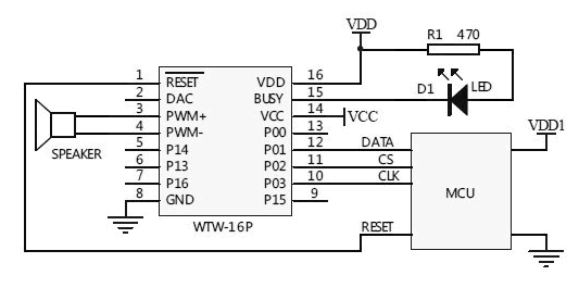
In plain terms: connect the WT588D’s BUSY pin to Arduino ground, the DATA pin to a digital output pin (pin 8 in the examples), and the CLK pin to a second digital output pin (pin 9). Power the WT588D from the Arduino’s 5V pin.
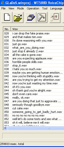
I’ve taken the time to download sound clips, modify, and organize a few themes.
- Games – sound effects for the mechanics and the animation, GLaDoS voices from the Portal video game
- Spooky – selection of spooky sounds for Halloween projects.
- LCARS – Star Trek computer phrases and sounds.
- Zelda: Link To The Past – sounds from the video game.
Other themes online:
Parts:
- Arduino Nano
- Expansion Board
- USB to mini USB ~ 5ft. cord
- AC/DC Outlet Power Adapter
- Project Box
- WT588D Sound Module
- 8 x 7-segment Display module
- (1-4) strips of 10 RGB 12mm LEDs.
- (2) push-buttons
- photocell (a light-dependent resistor whose resistance changes based on ambient light)
- microphone
- PIR sensor (a motion sensor that detects infrared heat from moving people or animals)
Steps:
Prepare the following for wiring and connect to the expansion board:
- WT588D with wiring harness and speaker
- (1-4) strips of 10 RGB 12mm LEDs.
- 8 x 7-segment Display Module
- (2) push-buttons
- photocell
- microphone
- PIR sensor
Connect the push-buttons to the expansion board and upload test code.
Connect strips of 10 RGB 12mm LEDs to the expansion board and upload test code.
Connect the 8×7 segment display module to the expansion board and upload test code.
Any sensor can be used to trigger specific or random sounds and going even further, a basic neural network could make decisions using multiple sensor inputs.
Connect the photocell (a light-dependent resistor whose resistance changes based on ambient light — lower in bright light, higher in darkness) to the expansion board and upload the test code.
Connect the Microphone to the expansion board and upload test code.
Connect the PIR sensor (a motion sensor that detects infrared heat from moving people or animals) to the expansion board and upload the test code.
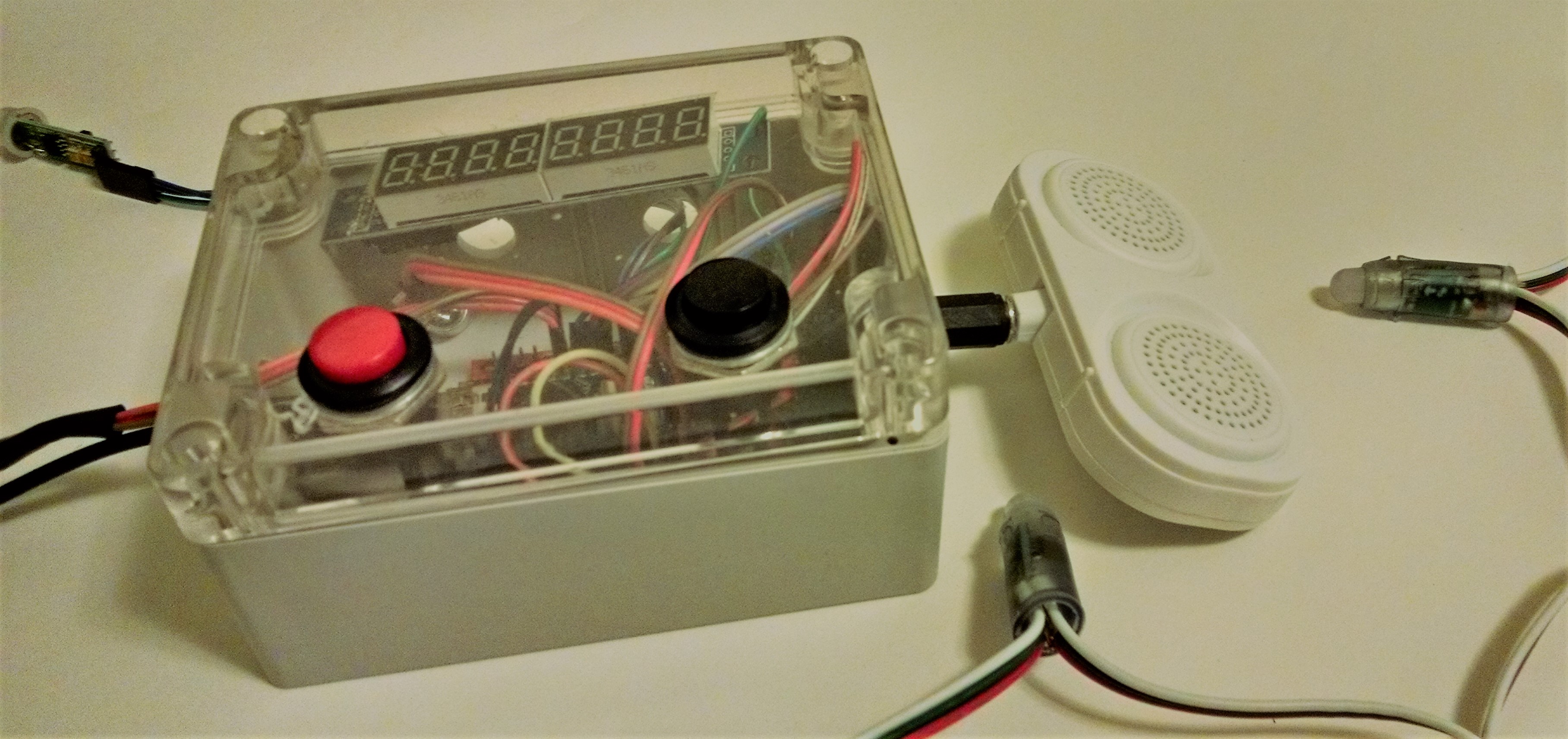
Insert Arduino Nano into Expansion Board and plan to provide power using USB to mini USB cord. Optionally, AC/DC Outlet Power Adapter
Enclosing the project
Drill 7/16” – 1/2” holes into the project box:
HOLE 1: side
USB to mini USB ~ 5ft. cord
Optionally, AC/DC Outlet Power Adapter
HOLE 2: cover push-button
HOLE 3: cover push-button
top front side
HOLE 4: (1-4) strips of 10 RGB 12mm LEDs
HOLE 5: speaker connector
HOLE 6: side
microphone, PIR sensor